Table Of Content
- The Drag Curve
- NASA-Led Study Provides New Global Accounting of Earth’s Rivers
- Mastering Lift: The Design Of Airplane Wings
- Aspect Ratio
- NASA Grant Brings Students at Underserved Institutions to the Stars
- Anduril and General Atomics to Develop New Collaborative Combat Aircraft for Air Force
- The 6 Best Flight Simulator Yokes, Pedals & Controls [Updated 2024]

Much of the seminal work on airfoil theory was due to German scientist Max Munk, who had been brought into NACA’s Langley laboratory as a technical advisor in 1920 and eventually became chief of aerodynamics. Munk, whom an official history describes as “simultaneously an aerodynamical wizard and an unstable charlatan,” proved to be a difficult person to work with or under. He was dictatorial, rigid, obsessed with hierarchy, insensitive to people, and, because of an incomplete command of English, sometimes incomprehensible.
The Drag Curve
The primary purpose of using dihedral is to improve the aircraft’s lateral (roll) stability; usually, only a few degrees are needed to enhance stability significantly. The horizontal tail may also have some dihedral, especially on larger aircraft, contributing somewhat to the lateral stability. Some amount of dihedral will come from wing-bending structural displacements. Airfoil sections may also be used to introduce an aerodynamic twist along the wing span. The effects obtained are usually combined with a geometric twist to achieve the desired spanwise lift distribution to meet aerodynamic performance and other goals.
NASA Has a New X-Plane With Unusual Wing Design, They Call It X-66A - autoevolution
NASA Has a New X-Plane With Unusual Wing Design, They Call It X-66A.
Posted: Tue, 13 Jun 2023 07:00:00 GMT [source]
NASA-Led Study Provides New Global Accounting of Earth’s Rivers
They are internally supported by structural members and the aircraft’s skin. Angling the wings up or down spanwise from root to tip can help to resolve various design issues, such as stability and control in flight. To support itself a wing has to be rigid and strong and consequently may be heavy. Originally such bracing was always present, but it causes a large amount of drag at higher speeds and has not been used for faster designs since the early 1930s.
Mastering Lift: The Design Of Airplane Wings
They reduce wingtip vortices, which is air whipping in a circle behind a wing in the action of creating lift. Wingtip vortices are frustrating to aeronautical engineers because they counteract the very generation of lift. Winglets, however, through their placement on the tips of airplane wings, help to “calm” the air and lessen drag.
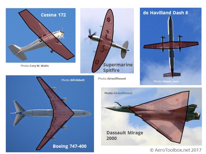
Aspect Ratio
Why would these two aircraft be designed with such a large variation in aspect ratio? The Cessna has a cruise speed of 122 knots true (KTAS) while the Dash 8 is significantly faster at 360 KTAS. Each is a very different size and shape, and designed to fulfill a very different mission. Take a moment to look over each one and see if you can spot and describe how they differ geometrically. An example of the distributed lift load and resulting shear and bending moment diagrams arising from this loading is shown below.
Ogive wings offer excellent performance at supersonic speeds with minimal drag. The main advantage of a delta wing is that it is efficient in all regimes (supersonic, subsonic, and transonic). Moreover, this type of wing offers a large area for the shape thereby improving maneuverability and reducing wing loading. The chord of the wing is varied across the span for approximate elliptical lift distribution.
Anduril and General Atomics to Develop New Collaborative Combat Aircraft for Air Force
The aspect ratio is then simply calculated as the wing span squared, divided by the wing area. If you’ve spent any time looking at pictures of airplanes or taken a walk around an airport you may have noticed that there is an enormous variation in the size and shape of the wings attached to each aircraft. The trailing edge of the wing sweeps forward while the leading edge sweeps back.
Wings intended for fast, maneuverable, highly-stressed aircraft like fighters tended to be thin and to have an aspect ratio of five or six. Those designed for transports—bombers, cargo haulers, and airliners—used higher aspect ratios, often 10 or more, and, in order to accommodate the necessary internal structure, they were thick in profile. The cross-sectional areas of the spar caps determine how much load each can support.
Biplane wings together formed a bridge-like truss that distributed stresses evenly across the span. Unbraced cantilever monoplane wings, on the other hand, experienced extremely large stresses where the wing met the fuselage. In order to cope with them, it was desirable both to make the root thicker than the tip and also to reduce the amount of lift being produced far outboard. Monoplane wings were therefore almost always tapered in both width and thickness. The wings of subsonic airplanes consequently fell into two broad categories.
The size and intensity of the circle in which the wingtip vortices operate is reduced. The view is looking out towards the right wing tip and the cloth skin has been removed from the wing so that the construction can be viewed. The spars are long, heavy pieces that run from wing tip to wing tip along the leading edge and near the middle of the wing. The ribs are attached to the spars and the ribs produce the airfoil shape.
As with the shear flow analysis, the mathematics behind this calculation are complex and outside of the scope of this tutorial. Instead we briefly introduce the rationale behind a collapse moment analysis. This is the classical approach to aircraft structural design and will result in an efficient structure that has been sized with conventional methods which are well accepted by the certification authorities.
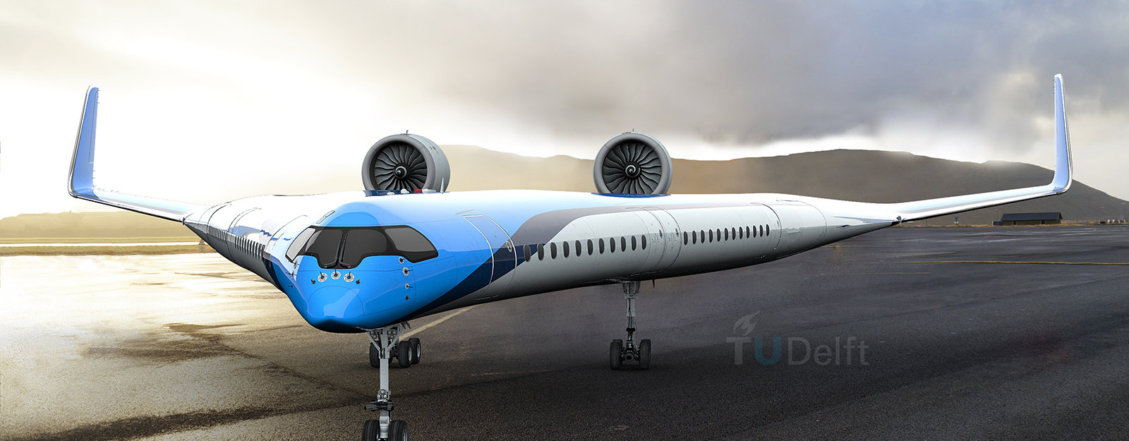
The result is an aircraft with the passenger capacity and range of a small wide body that uses the engines of existing narrow-body planes. This breakthrough fills the mid-market gap with an aircraft that achieves half the fuel burn and emissions of the aging fleet it will replace. The Blended Wing is a naturally stable design requiring no tail surfaces, which eliminates unnecessary complexity. A shorter, wider fuselage is blended together mimicking the wing to provide lift. This reduces the surface needed, creating a lighter aircraft with less drag.


No comments:
Post a Comment